Husky
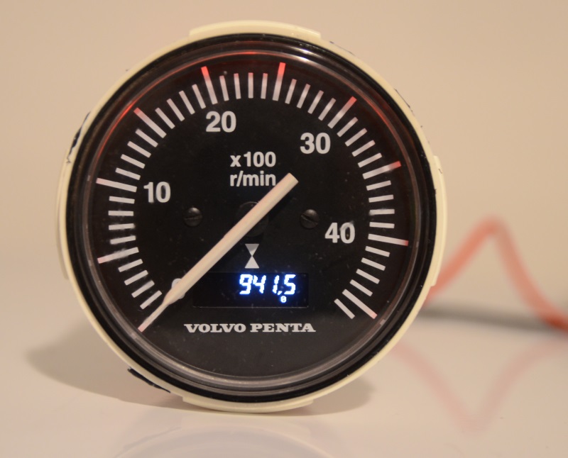
VDO Hour Meter Repair
This is my solution to fix the display on a combined VDO tachometer/hourmeter, which
is used in many OEM installations, including Isuzu, Volvo Penta, Yanmar, and many others.
Software (complete, with source code), and mounting instructions can be found below.
My solution is based on an idea from a member (Stuart) on the
Canal World
Forums. You can find additional background information including some details
of how to fit everything in the VDO enclosure there.
- Update April 2022
- This repair has now been running for seven years on my boat without any issues.
- Update February 2020
- It seems that www.boatstuff.se has stopped selling the replacement displays, but
you can find some Chineese version on ebay for about 20 USD.
Meanwhile I've got some requests for supporting a 128x32 Arduino OLED display and
moving the text to a different position on the display, so I've made a new release 3
you can find below.
Conor McLoughlin has written an excellent document showing how he has installed the
128x32 OLED display in a Yanmar VDO hour meter. It seems to be a smaller unit than
mine, hence the smaller display is required.
His writeup can be found here.
- Update December 2016
- This repair has now been running for two years on my boat without any issues.
Initially I was a bit worried about the OLED and humidity combination, but it does
not seem to be a problem. Also the hour meter is very easy to read at night, and
a bit difficult to read during daylight. However I have a hunch that the original
display would be no better during daylight, and certainly much worse during night.
Also note that boatstuff.se started selling replacements of the original display
in the spring of 2016 (they have since stopped selling them). They're quite pricy,
though at ~65 EUR, and they'll likely also have a limited lifespan. The proposed
OLED solution shown here should be well below 10 EUR.
- Arduino code for VDO repair
- Use this code to have the Arduino Nano convert the 7-segment LCD memory map to
OLED memory map.
If you find this useful, a small donation would be greatly appreciated :-)
Use the contact form to request my paypal account.
Of course you can also use the contact form if you have any questions!
|
|
|
Release 3 (February 2020)
To use:
1. Install the Arduino IDE.
I used version 1.8.11, but newer versions probably works too.
2. Import the OLED directory as an Arduino library
3. Compile and download this sketch
4. Enjoy
Release 3 has now been uploaded, it has the following improvements:
- Works with current Arduino IDE (1.8.11)
- Supports 128x32 OLED display (along with 128x64 OLED display, as before)
- Supports vertical adjustment of the image on the display
- Option to flip display 180 degrees
- Fixed a bug where 7 was shown incorrectly on some VDO displays when using Arial style font
Note that the OLED library has changed from the previous releases, so if you already
installed the release 1 or release 2 version you have to manually overwrite the files
in your "My Documents/Arduino" folder.
Also note that the splash screen tool has changed from the previous release, so make sure
you use the one provided with this release. It is also called "Release 3" in an
attempt to cause less confusion.
Download the "release 3" Arduino code
Unless I get feedback about problems or feature requests I consider this the final version.
|
|
|
Release 2 (January 2015)
To use:
1. Install the Arduino IDE version 1.0.6
Note: It has to be version 1.0.6 as the newer 1.6 series uses
an new GNU compiler, which seems to be incompatible with older code, including this.
2. Import the OLED directory as an Arduino library
3. Compile and download this sketch
4. Enjoy
Release 2 has now been uploaded, it has the following improvements:
- Nicer Arial style font
- 7-segment font
- A tool to convert a picture into a startup splashscreen, so you can have
the name of your boat shown on startup
Note that the OLED library has changed, so if you already installed the release 1
version you have to manually overwrite the files in your "My Documents/Arduino"
folder.
Download the "release 2" Arduino code
|
- Possible Improvements
-
- Put Arduino to sleep mode.
- Power consumption has been increased quite a bit with the LED and Arduino. Hopefully not too much!
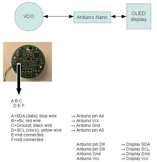
- Connections
-
First connect the Arduino to the OLED display, as shown in the diagram below. Then download the
code. When everything is good to go, connect the VDO unit to the Arduino.
Note that the Vin pin should not be used as it is connected to a power regulator. Instead
you can use the Vcc pin and there is a second Vcc pin in the 6-pin ISP programming header, if
you don't want to connect two wires to the same hole (it's not really meant for two wires, so it's
not super-easy to fit).
When the Arduino Vcc is connected to the VDO display you need to have 12V power on the VDO unit
while the USB cable is connected to the Arduino. Otherwise the VDO unit is drawing too much current
from the USB connection so the Arduino will not function. Your Arduino Nano should have a diode
between the USB power and Vcc, which means that it is safe to connect USB power while the VDO
powers Vcc on the Arduino. However it is possible that certain cheap knock-offs are not fitted
with this in order to save two cents, so be careful!
Btw: I used an Arduino Nano without pin headers mounted. There was not enough room in my VDO
case for the pins to fit.
- Diagram
-
- Pictures
-
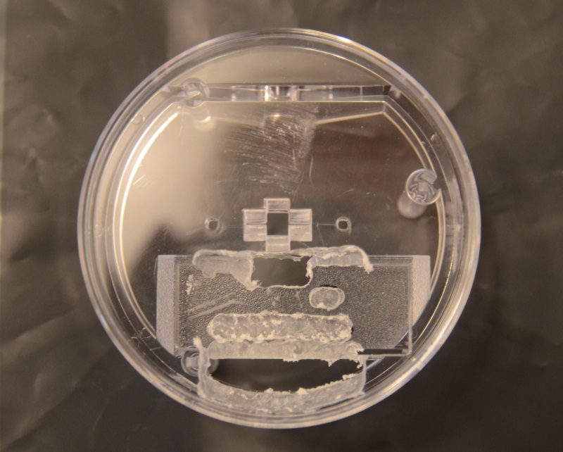
The transparent plastic milled to fit the OLED display. I deliberately tried to avoid cutting
the outer circular part. It is used to reflect the red light onto the unit. The hole is for
the wires and the deepeed areas are because some of the capacitors are a little raised. I
used a Proxxon tool with a suitable milling bit.
|
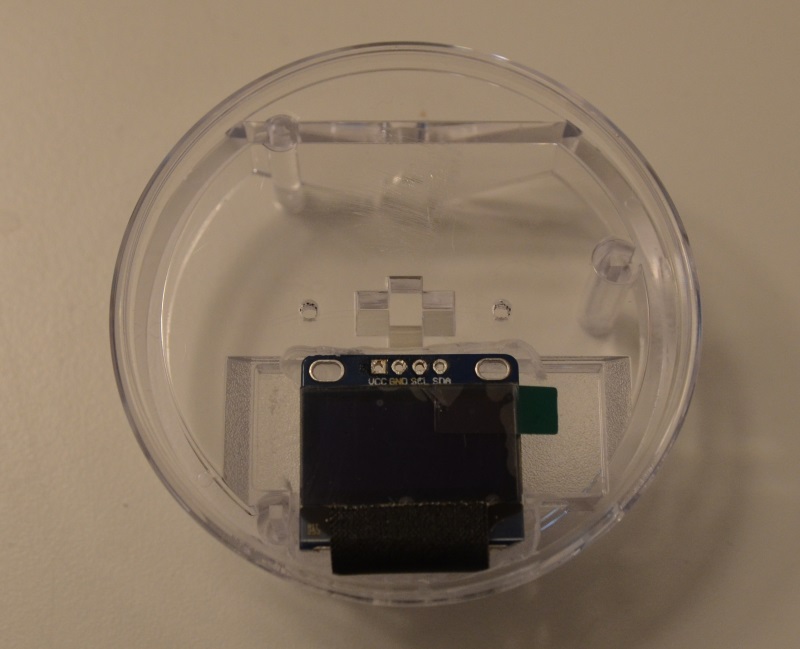
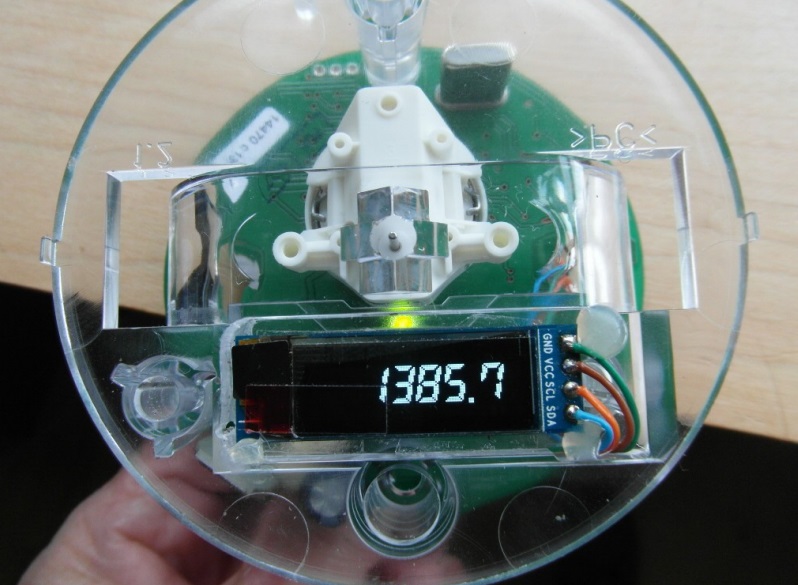
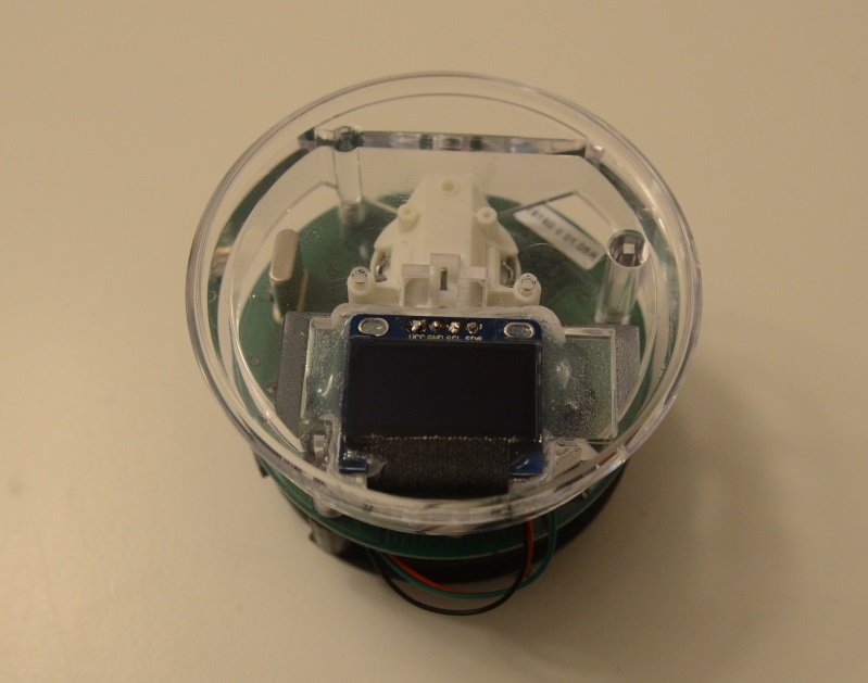
OLED display fits perfectly!
|
Cover added. The protective film on the OLED display is still fitted.
|
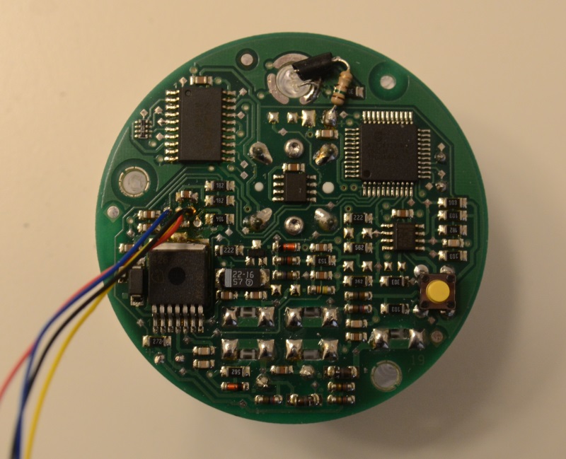
The PCB with wires and LED mounted.
|
The PCB with the high bright red LED mounted.
|
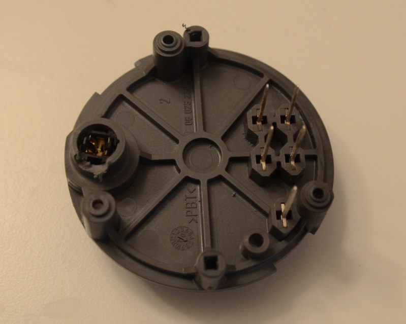
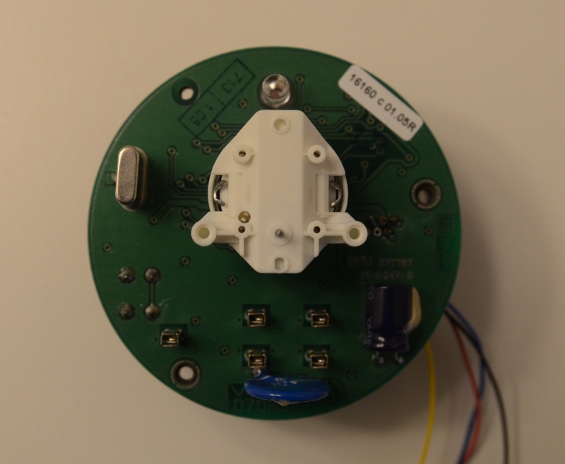
I had to mill the rear cover a little in order for the LED connections to fit.
|
Mounted and glued. I used silicon coating, but you can use any glue.
|
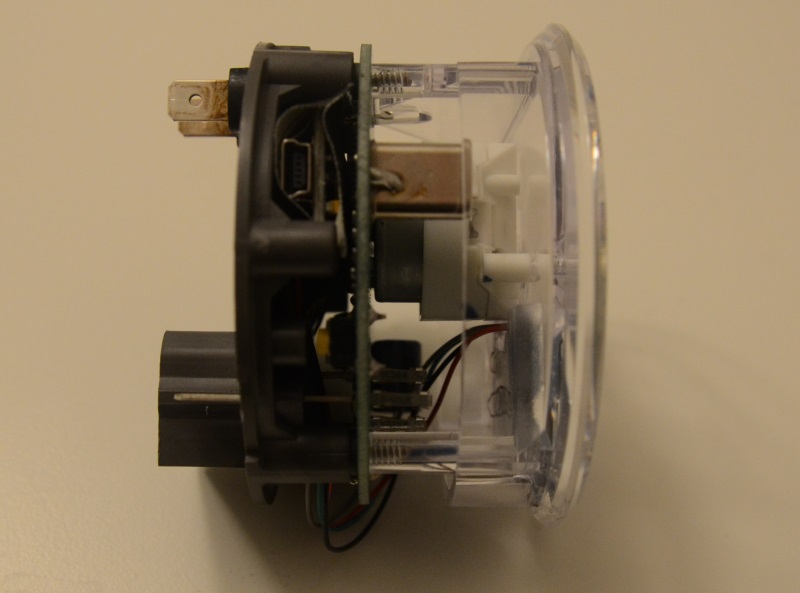
It just barely fits with the Arduino!
|
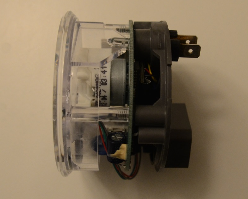
From the other side.
|
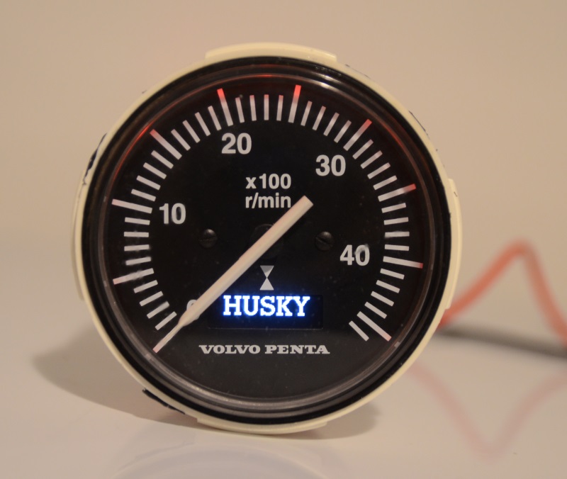
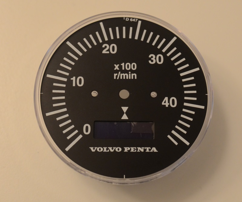
Powered up with the custom logo. You can easily create your own using Paint
and the tool I created.
|
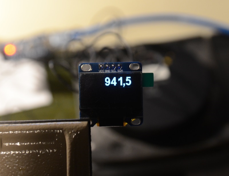
Hour counter now working.
|
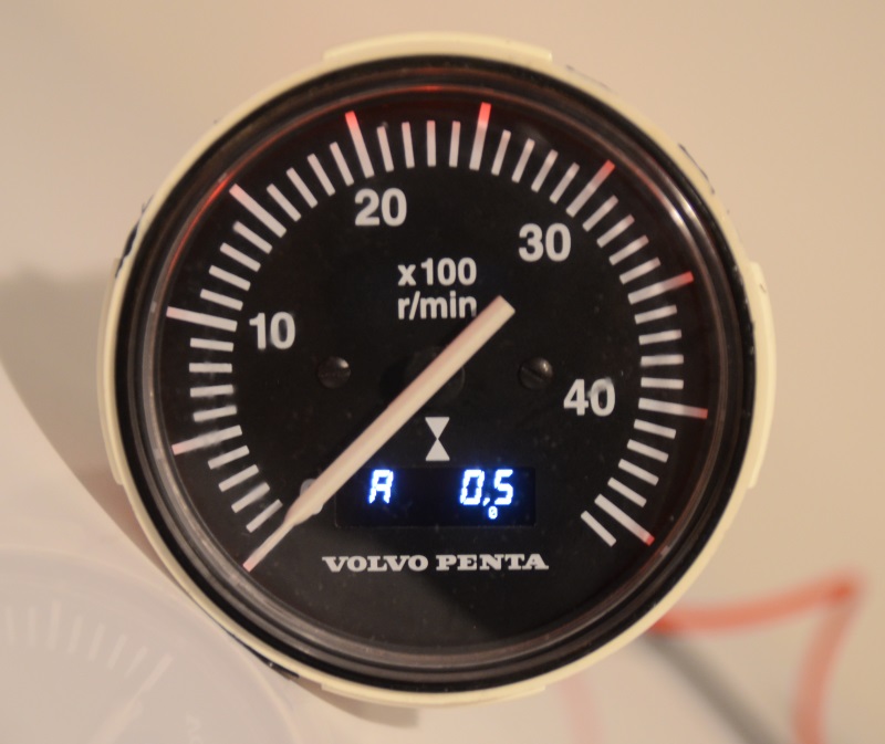
The VDO programming modes also work.
|
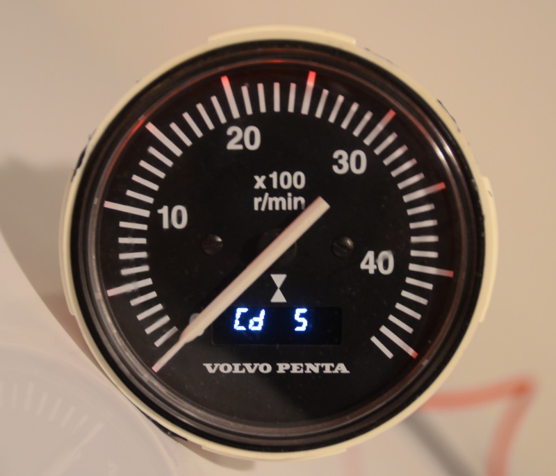
The VDO programming modes also work.
|
One picture of the arial style font. I forgot to take it after putting the instrument
together..
|
|